- Published on
Spent fuel matrix alteration model under Deep Geological Repository conditions
- Authors
Author
- Name
- Olga Ribamail

The safety assessment of deep geological repositories (DGR) for used spent fuel (SF) requires a fundamental understanding of the processes controlling fuel alteration and the release of radionuclides into the geosphere.
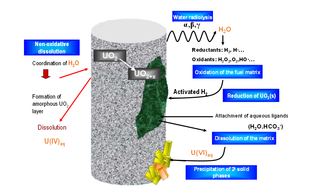
The corrosion of the containers in which the spent fuel is stored will eventually lead to container failure and groundwater inflow. Water entering the failed container will be devoid of oxygen due to the corrosion of steels and cast iron, ensuring a low redox potential by the production of H2 and Fe(II). Subsequently, the oxygen depleted water will get in contact with the spent fuel experimenting radiolysis by the effect of alpha radiation (emitting gamma and beta fission products are expected to be decayed at repository times greater than 10.000 years, when failure of the container is expected). Water radiolysis generates both oxidizing and reducing species in solution: H+, OH-, O2, H2O2, H2, HO2-, HO2·, O·, O-, O2-, H·, ·OH and e- [1]. Taking into account that the reducing effect of H2 is inhibited by its slow kinetics, radiolysis could potentially lead to relatively fast oxidative dissolution despite the bulk reducing environment. However, some fission products contained in the irradiated fuel have shown to be able to activate H2 through their catalytic effect. We refer to the epsilon particles (Rh, Pd, Ru), whose catalytic effect can result in low H2 concentrations, suppressing the oxidation of UO2 [2-4]. The high complexity of the described system is schematically represented in Figure 1.
In the framework of EURATOM Project “DisCo” (modern spent fuel Dissolution and chemistry in failed Container conditions), carried out within the Horizon2020 framework program, Amphos 21 has integrated the processes occurring at the spent fuel surface (see Figure 1) with a 1D reactive transport model. The model has been implemented in iCP [5], using the two-way coupling approach shown in Figure 2.
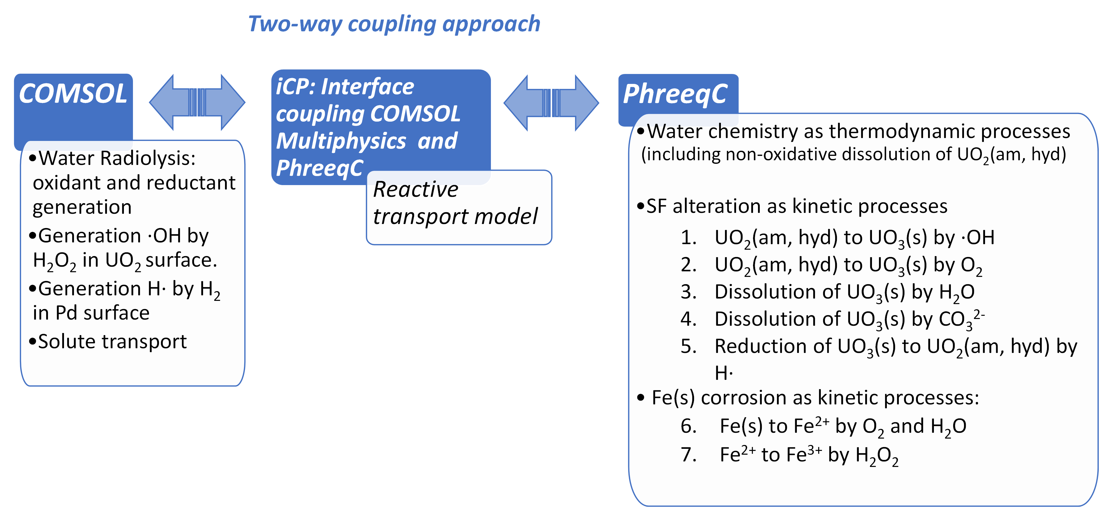
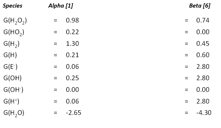
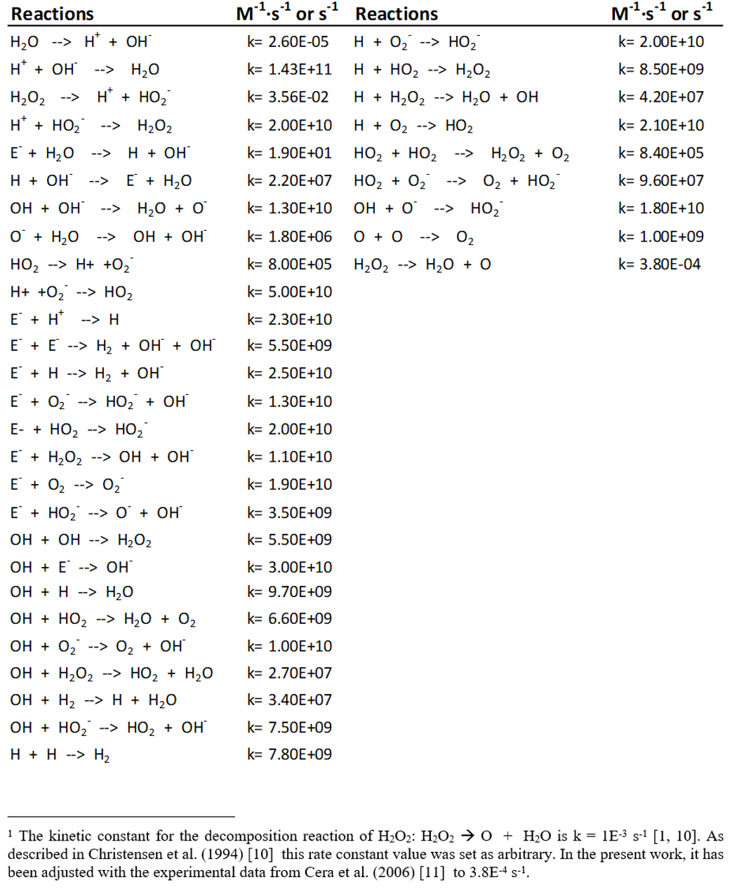
The complete water radiolysis scheme, integrating more than 35 kinetic reactions together with the yields of primary products [1, 6] (included in Appendix 1) has been implemented in COMSOL though a set of ordinary differential equations (ODE) and were coupled with the solute transport equation (Eq. 1) through a source term in Riba et al. (2020) [7].
The SF matrix has been modelled as amorphous UO2 with a homogeneous chemical composition and containing 1 atom % of Pd, as representative element of the epsilon particles. The kinetic reactions related to the alteration of SF and Fe(s) corrosion are implemented in PhreeqC (see Figure 2).
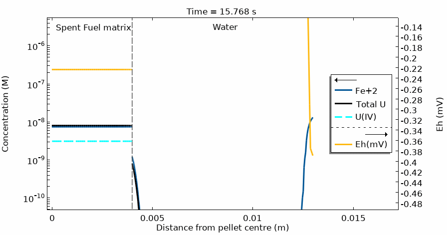
The interrelated processes described above have been implemented in a 1D model with the geometry presented in Figure 3 to simulate a DGR concept where the iron insert of the copper canister is at 10 mm from spent fuel rods [8]. A uniform alpha dose rate of 2.86·10-2 Gy·s-1 affecting the first 13 μm in water adjacent to the SF surface was assumed in the 1D simulation. This uniform alpha dose rate is equivalent to a non-uniform exponential distribution of dose rate affecting 35 μm in water adjacent to the SF surface, in the sense that both produce the same total dose rate [9].
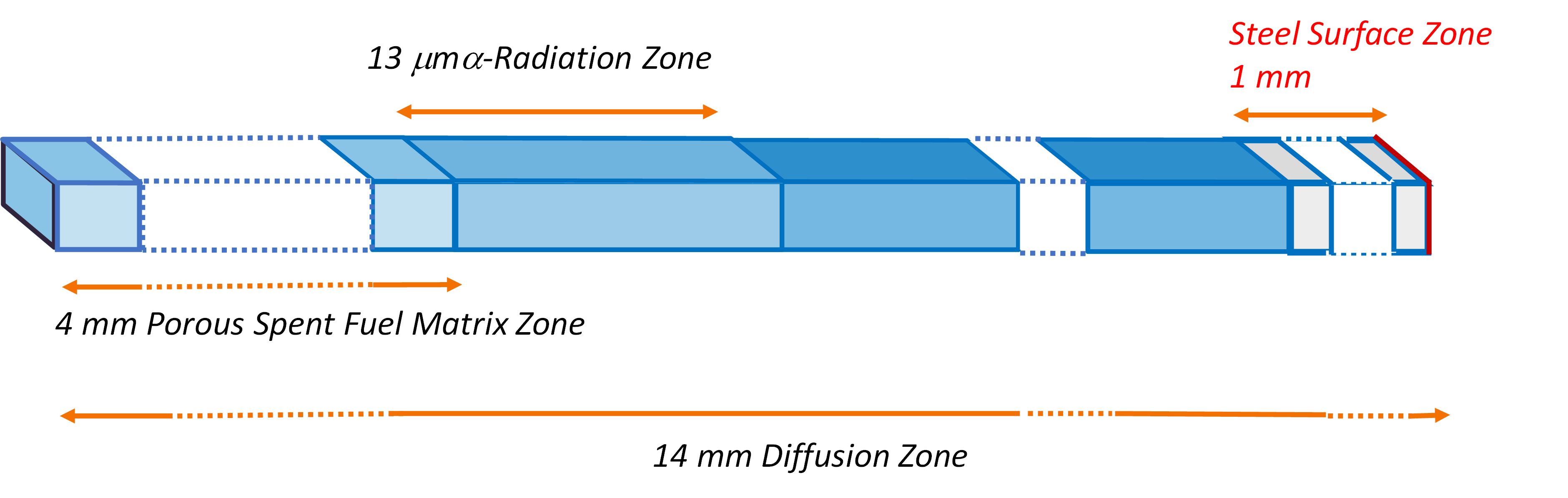
Figure 4 shows the temporal evolution of the total U, U(IV) and Fe2+ concentration profiles. The total U concentration is in accordance with the Eh in the different domains and at different simulation times. Notice the sharp increase of both [U] and Eh after 20 days of simulation time.
This modelling approach has solved the challenge of coupling the complete water radiolysis system with chemical complexation reactions and dissolution/precipitation processes which occur at very different time scales, often with rates differing by more than 6 orders of magnitude.
The model not only integrates the radiolysis of water but also these two important systems: uranium (as the main element of the fuel) and the iron of the steel-container and metallic insert, having, both of them, a very complex chemistry. Also, it has the flexibility for future inclusions of other chemical processes to account for the complex system of SF, steel container and water chemistry. Therefore, it represents a step forward towards the development of the models needed to assess the performance and the safety of a DGR for spent nuclear fuel.
References
[1] Kelm, M., Bohnert, E. (2004) A kinetic model for the radiolysis of chloride brine, its sensitivity against model parameters and a comparison with experiments, Forschungszentreum Karlsruhe, FZKA 6977.
[2] Carbol, P. Fors, T.Gouder, K. Spahiu (2009). Hydrogen suppresses UO2 corrosion. Geochimica et Cosmochimica Acta 73 (2009) 4366–4375.
[3] Trummer, T., M. Jonsson M, J. (2010). Resolving the H2 effect on radiation induced dissolution of UO2-based spent nuclear fuel Nucl. Mater., 396, 163–169.
[4] Ollila K (2011). Influence of Radiolysis on UO2 Fuel Matrix Dissolution Under Disposal Conditions - Literature Study. Posiva Working Report 2011-27, 64 pp. Posiva Oy, Olkiluoto, Finland.
[5] Nardi, A., Idiart, A., Trinchero, P., de Vries, L. M., and J. Molinero (2014). Interface COMSOL-PHREEQC (iCP), an efficient numerical framework for the solution of coupled multiphysics and geochemistry. Computers & Geosciences 69: 10-21.
[6] Eriksen, T. E., Jonsson, M., Merino, J. (2008). Modelling of time resolved and long contact time dissolution studies of spent nuclear fuel in 10 mM carbonate solution–a comparison between two different models and experimental data. Journal of Nuclear Materials, 375(3), 331-339.
[7] Riba, O., Coene, E., Silva, O., Duro, L. (2020). Spent fuel alteration model integrating processes of different time-scales. MRS Advances, 5(3), 159-166.
[8] Raiko (2012). Canister design 2012. Posiva Report 2012-13.
[9] Wu, L., Beauregard, Y., Qin, Z., Rohani, S., Shoesmith, D. W. (2012). A model for the influence of steel corrosion products on nuclear fuel corrosion under permanent disposal conditions. Corrosion Science, 61, 83-91.
[10] Christensen, H., Sunder, S., Shoesmith, D. W. (1994). Oxidation of nuclear fuel (UO2) by the products of water radiolysis: development of a kinetic model. Journal of alloys and compounds, 213, 93-99.
[11] Cera, E., Bruno, J., Duro, L., Eriksen, T. (2006). Experimental determination and chemical modelling of radiolytic processes at the spent fuel/wáter interface. SKB TR 06-07, Svensk Kärnbränslehantering AB.
Appendix A
Kinetic reaction scheme for water radiolysis [1]
Yields of primary products (mol·l-1 x 10⁷) formed on radiolysis of water