- Published on
Tunflow 1.0 - How to calculate groundwater inflow into tunnels and galleries
- Authors
Author
- Name
- Jordi Font

Background
Groundwater inflows into tunnels may constitute a potential hazard as well as an important factor controlling the rate of advancement in the excavation. In fact, one of the major practical difficulty during tunnel construction is often associated with the presence of groundwater. Predictions of groundwater inflows are also needed to design suitable drainage systems. Furthermore, drawdowns produced by tunnel construction may induce land subsidence, water table decline and environmental impacts on rivers and wetlands.
In the literature, there are several analytical expressions to calculate water discharges into tunnels but a major development was presented recently by Perrochet and Dematteis (2007). The program TunFlow makes use of the above-mentioned analytical expression to compute groundwater infiltration into tunnels and galleries. The program allows an unlimited number of geological zones (heterogeneous system) to be accounted for. Furthermore, fully transient hydrogeological conditions (accounting for the velocity of tunnel advancement) are considered. TunFlow is easy to use and is especially suited for the evaluation of groundwater filtrations in scoping studies for tunnels construction.
Input parameters
The analytical expression developed by Perrochet and DeMatteis (2007) to calculate the groundwater tunnel inflows and used in TunFlow is shown below:
The parameters of this formula are:
- [d]: time
- [m]: length of the section of a given geological layer
- [m/d]: drilling velocity
- [m/d]: permeability of the considered layer
- [1/m] Specific storage of the considered layer
- [m]: tunnel radius
- [m] level of water table (distance from the tunnel roof)
Before running the model, it is preferable to create an Excel sheet with all the information requested by the code. The numbers of layers is specified in the Graphical User Interface (GUI) of TunFlow (1 and 2, Figure 1).The number of time steps must be also selected (3, Figure1) . By default, 1000 time steps are used. It is worthwhile noting that increasing the number of time steps improves the accuracy of the solution but also increases the computational costs of the simulations (i.e. simulation time).
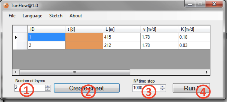
Once all the parameters are imported in TunFlow, the program can be executed (4, Figure 1).
Results and output options
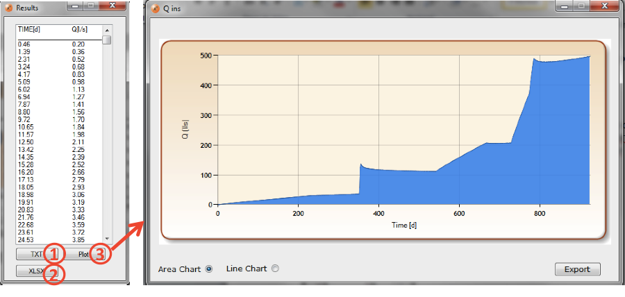
Tunflow provides diferent outputs. Calculated data can be exported in txt and xlsx file formats (1 and 2, Figure 2).On the other hand, the program also plots the results as the tunnel inflows Q (l/s) versus time (d) (3, Figure 2).
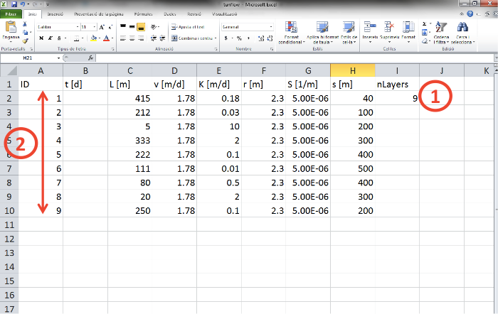
The input parameters can be also exported as an xlsx file (1 and 2 in Figure 3) and used for new simulation runs.
Acknowledgements
This work has been conducted at Amphos 21 in collaboration with Santos Jiménez, Paolo Trinchero and Jorge Molinero.
References
Perrochet, P., Dematteis, A., 2007. Modeling Transient Discharge into a Tunnel Drilled in a Heterogeneous Formation. Ground Water 45 (6), 786–790.